

When designing a silicone rubber keypad, it is important to consider how you want to apply force to the shorting pad, and how much force is needed. The simplest and most accurate method is by using metal domes. The use of metal domes within your keypad assembly eliminates the need for the use of a diaphragm and the need to generate a force curve diagram. However, in some cases, metal domes are not able to be used. This requires the silicone rubber keypad to create the force the customer is looking for. This is where the use of Diaphragms come into play. A Diaphragm is the thin hinged area of a keypad that allows the keypad to move and flex. Diaphragms are also known as Webbing or Webs. The act of pressing and depressing a silicone key that contains a diagram will generate a force curve.
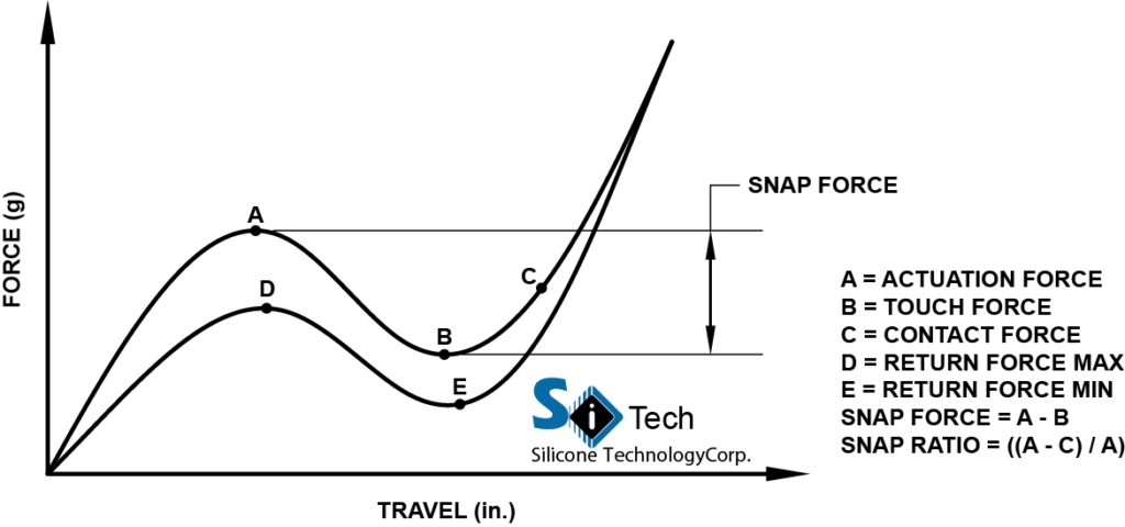
When determining the exact force you will require for your silicone rubber keypad, it is important to understand all of the variables that make up your force curve. Actuation force is the force required to collapse the diaphragm of a silicone key. Actuation force is depicted with the letter A on the diagram below. Next on the diagram is Contact force, which is shown with the letter C. Contact force is the amount of force required to maintain the closure of the silicone key.
Using the Actuation force, and Contact force, you are able to calculate a snap ratio for your silicone key design. The formula for determining the snap ratio is as followed: (Actuation Force – Contact Force) / Actuation Force, or (A – C) / A = Snap Ratio. The snap ratio of a silicone rubber key will directly affect the tactile response an operator receives. A silicone rubber keypad that has snap ratios of approximately 35-60% have an excellent tactile response and generally have a long work life. Keypads below snap ratios of 35% will have a weaker tactile response, but much longer work life.
The last force to determine is the return force. This is the force created by the keypad’s diaphragm as it returns to its neutral position. These are represented by letters D and E on the force curve diagram. Where letter D is the Return Force Maximum, and E is the Return Force Minimum.
All of these forces are determined by the design of the diaphragm. Different variations in thickness, angle, and travel will give different forces and a different curve overall.
Here at SiTECH, we have an extensive knowledge when dealing with liquid silicone rubber keypads and force requirements. If you are in need of assistance or would like some recommendations for your design you can contact us here or by phone at: 757-887-8488.