

Design Recommendations
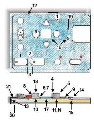
Mechanical Keypad:
 Distance of a key’s diaphragm to the edge of the keypad’s matte and any through hole is 0.040″.
- Minimum key pitch dimension is 0.080″.
- Distance between two diaphragms is 0.040″ (measured at base of diaphragm).
- The smallest blend radius of key’s side wall to top of key is 0.010″.
- Typical key taper is ³ 1° depending on key height.
- Typical chamfer dimension on tactile keypad is 0.020″.
- Typical chamfer angle on tactile keypad is 45.
- Clearance between a bezel to a key is 0.012″.
- Typical base (matte) thickness is 0.040″.
- Standard air channel geometry is 0.080″ to 0.125″ wide by 0.010″ to 0.013″ deep.
- Conductive contact area is 0.030″ based on keypad application and size.
- Sealing bead(s) top and/or bottom for environmental design requirements.
- Assembly aids via rattails and/or perimeter lip to hold rubber keypad to feature
- Through hole diameter is 0.025″.
- Corner radius on matte and key’s 0.015″.
 Distance of a key’s diaphragm to the edge of the keypad’s matte and any through hole is 0.040″.
Display/ LED lightpipe/ Window opening:
- Maximum depth of undercut for feature window opening is 0.250″.
- Underside lip for window opening is the depth of undercut(#14) x 0.660″.
- Minimum size for molded in silicone window/lightpipe is 0.060″.
- Minimum thickness for molded in silicone window is 0.030″.
- Minimum height for molded in silicone lightpipe is 0.030″.
- Minimum distance from window/lightpipe to and edge is 0.030″.
- Min / Max. wrap around underside is 0.060″ to 0.500″. Deeper wraps may be considered depending on design.
- Sealing rib diameter is 0.030″.
Keypad Wrap – Around Design:
The wrap-around design offers unique capabilities in silicone rubber. Using liquid injection process, one can create hand held units similar to complete plastic cases. With the wrap-around feature, an appealing product can be designed with all the protection requirements for harsh environments.
Typical Part Tolerances
| Dimension | Tolerance |
| <0.400 0.401-0.800 0.801-1.200 1.201-1.600 1.601-2.000 >2.001 |
0.004 0.006 0.008 0.010 0.012 0.6% |
Digital Mechanical Designs:
Distance of a key’s diaphragm to the edge of the keypad’s matte and any through hole is 0.040″.Si Tech has the capability to accept 2D and 3D solid modeling designs created with softwares like Autocad, ProE, Solidworks and using several file type formats including:
- * .dwg
- * .dxf
- * .smt
- * .iges
- * .x_t
- * .prt
- * .sat
- * .vda
- * .prt
- * .step
- * .x_b
- * .sldprt
Continue to our next Application Guide page: Graphic Design Considerations